how we built
a chassis dyno
Dyno testing and reliability of results
While dyno graphing software can monitor and compensate for variations in temperature, barometric pressure, intake air and exhaust gas temperatures, etc., it cannot reliably compensate for inaccurate feedback from the roller itself. When a roller lacks precision or is prone to vibration, spikes in torque and speed will randomly appear in the test results. When this random data contaminates test results, accurate tuning becomes problematic. For example, air and fuel flow adjustments are fine-tuned based upon the data generated by repeated passes on the dyno. But how can these adjustments be made accurately when the dyno results are inconsistent?
By installing a roller with a precision of 0.00001 inches and paring it with vibration-free bearings and pillow blocks on concrete footings, we eliminate these false torque and speed spikes so that our test data that can be consistently replicated from pass-to-pass and our technicians can fine-tune engines with accuracy.
Building the chassis dyno
We chose to build an in-floor chassis dyno instead of a more vibration-prone floor-top system to ensure the platform would be stable enough to produce valid and reliable data. The final product is a chassis dyno that can test everything from a 300cc motorcycle to a 14L tractor-trailer. If it can fit through the door, we can test it!

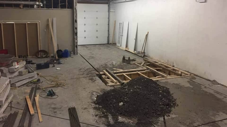
Excavation & Footings

Bearings

Pillow Block

Inertia Roller
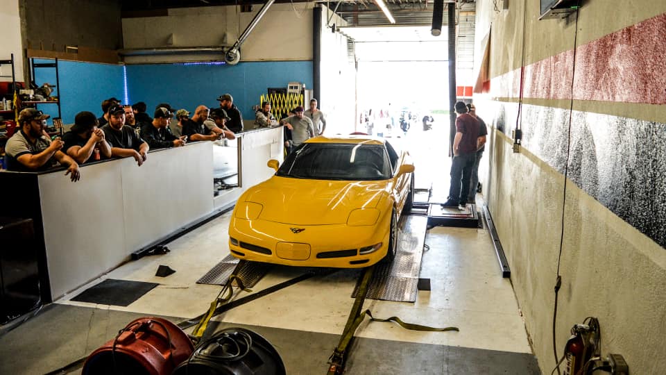
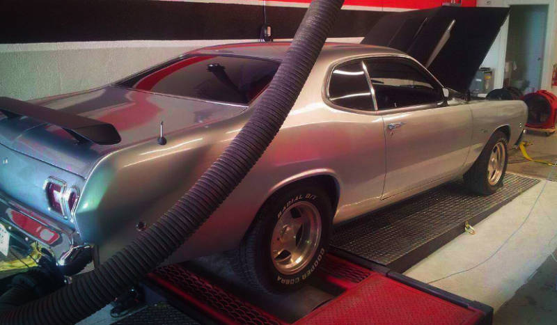
Our tether straps have a tensile strength of 3,335 lbs. and our fans push 10,000 cf/m to control engine temperature during testing. To keep everyone safe from emissions, our exhaust venting system has an air-handling capacity of 2,000 cf/m.
dyno testing and validity of results
Our dyno roller has a diameter of 24.5,” a mass of 2,500 lbs, and generates 2,278 ft. Lbs. of inertia. Having a large, high-inertia dyno that can roll at a rate of 8,000 RPM ensures that our test results are not only reliable but accurate.
Accurate tuning relies on the dyno’s ability to simulate the traction that vehicles experience in the real asphalt world. Small, low-inertia dynos aren’t able to adequately simulate road-load conditions or deceleration (coast-down) because the rollers don’t provide enough traction and they decelerate too fast.
Horsepower calculations are also skewed on these smaller setups because of wheel slippage and tire deformation. The tire deformation occurs when operators attempt to compensate for tire slippage by applying excessive strap force. While the extra pressure reduces the slippage, the flexing of the tire negates the validity of any reduction in slippage – and can cause sidewall damage to your tires.
From construction to the 2017 Dyno Day
click on image or drag handle for before/after pic


share this page
 Marc Chartrand
Sergiy
